



Product overview
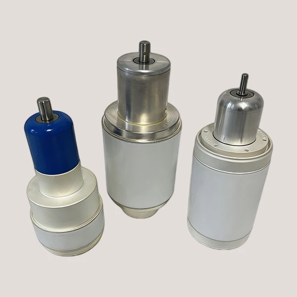
A variable vacuum capacitor changes capacitance by moving one electrode group relative to another inside a sealed vacuum body. It is installed in long-wave, medium-wave and short-wave transmitters, RF matching networks, high-frequency induction heating systems, medical RF equipment and other high-voltage tuning or neutralization circuits. Unlike a fixed model, it is used when capacitance must change during setup, frequency selection or load matching.
Specifications
|
Specification |
ZK-B-010 |
ZK-B-007 |
|
Type |
Variable vacuum |
Variable vacuum |
|
Capacitance (pF) |
Cmin <15 |
Cmin <10 |
|
Upt / Upw (kV) |
Upt 28 / Upw 20 |
Upt 10.5 / Upw 7.5 |
|
Max. RF Current @13.56 MHz (A) |
120 |
60 |
|
Max. Torque / Tuner Turns |
0.5 N·m |
0.2 N·m |
|
Max. Weight (kg) |
- |
1.5 |
|
Overall & Body |
Overall L 270 ± 3 |
Overall L 208 ± 1 |
|
Shaft / Terminal |
Shaft Ø16; cross-hole Ø4 |
Shaft Ø16; cross-hole Ø4 |
|
End / Flange Dimensions |
Left section 53; right 36 |
Left 34 + lip 4; right 24 + lip 4 |
|
Mounting Interface |
6-M6; thread depth 8; hole depth 10; EQS |
6-M4; thread depth 5; hole depth 6; EQS |
Core advantages
Tuning ranges extending to 400 or 500 pF
The two listed models tune from below 10 or 15 pF to 400 or 500 pF. In RF matching and induction-heating circuits, this span lets the same capacitor cover setup changes and load variation within the selected model range.
Up to 20 kV working voltage and 120 A RF current
The higher-rated model combines 20 kV high-frequency peak working voltage, 28 kV peak test voltage and 120 A at 13.56 MHz. This supports tuning positions where substantial RF voltage and current occur at the same operating point.
23 to 26 turns for controlled adjustment
Mechanical travel is distributed over 23 or 26 turns with maximum torque of 0.2 to 0.5 N·m. Near resonance, the multi-turn mechanism provides smaller capacitance changes per shaft movement than a short-travel adjustment.
Structure and materials
The capacitor consists of a ceramic vacuum envelope, metal end fittings, concentric oxygen-free copper electrode groups and an external adjustment mechanism. One electrode group remains stationary. The other moves axially, changing electrode overlap and capacitance.
A metal bellows, or an equivalent motion seal, carries the mechanical movement through the enclosure without breaking the vacuum boundary. Shaft, bearings, terminals and mounting parts are selected for the required travel, tuning direction and installation method. Models carrying higher current may also have a dedicated cooling connection.
Custom options
Capacitance range and tuning response
The custom specification can define minimum and maximum capacitance, adjustment ratio, mechanical travel and number of turns. The useful range is then checked against the equipment frequency band and circuit load.
Drive, cooling and installation interface
Shaft shape, tuning direction, mounting dimensions, terminal position and connection method can be adjusted for the equipment layout. The cooling arrangement is selected separately according to RF current and the amount of heat that must be removed.
Quality control
Electrode alignment and sealing
Before sealing, the fixed electrodes, moving electrodes, bellows and drive parts are assembled to the confirmed model. Alignment and travel are checked through the intended movement so the electrodes do not touch, overlap unevenly or interfere with the ceramic body.
Electrical and mechanical checks across the range
Capacitance is measured at several positions across the range, including intermediate points. Insulation, voltage withstand, adjustment continuity and mechanical operation are also checked before the finished capacitor is assigned to its production batch.
Manufacturing basis
A separate assembly route for variable structures
Variable capacitors are built on their own assembly route; they are not fixed capacitors with an adjustment part added later. Moving electrodes, bellows, drive components and the vacuum envelope follow a sequence developed for the approved tuning structure.
Sample and batch production in one facility
Wanping's in-house R&D team reviews the electrical rating, equipment fit and mechanical layout before a sample is built. Once the sample is approved, its drawing, model and configuration are used for batch production in the same facility.
FAQ
Q: How long does a custom variable vacuum capacitor sample take?
A: A regular custom sample normally takes about 40 to 60 days. Development may take longer when the design includes a new electrode system, special cooling arrangement or non-standard mechanical interface.
Q: What is the production lead time for an existing model?
A: An existing model normally takes about 20 to 40 days to produce, depending on the model and the current production schedule. Repeat orders are arranged against the specification confirmed for the earlier order.
Q: Can the capacitor be adjusted while the equipment is energized?
A: Only use the insulated or remote tuning mechanism designed into the equipment. Do not touch an exposed shaft or terminal while the high-voltage circuit is energized.
Q: Does every variable vacuum capacitor require water cooling?
A: No. Cooling depends on RF current, duty cycle and the airflow around the capacitor. Natural-convection models are used within their thermal limits; higher-current applications may need a water-cooled design.


Hot Tags: variable vacuum capacitor, China variable vacuum capacitor manufacturers, suppliers, factory, capacitor, High Voltage Ceramic Capacitor, Vacuum Capacitor, Variable Tuning Capacitor, Compact Capacitor, High Voltage Variable Capacitor


